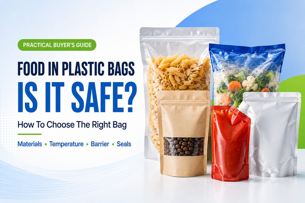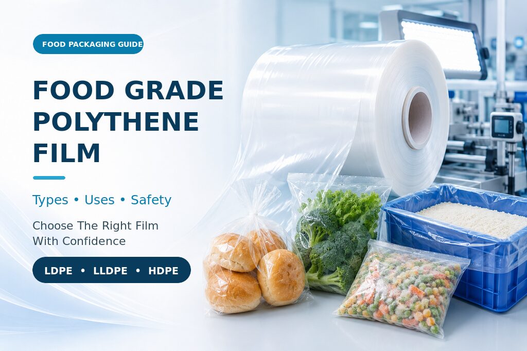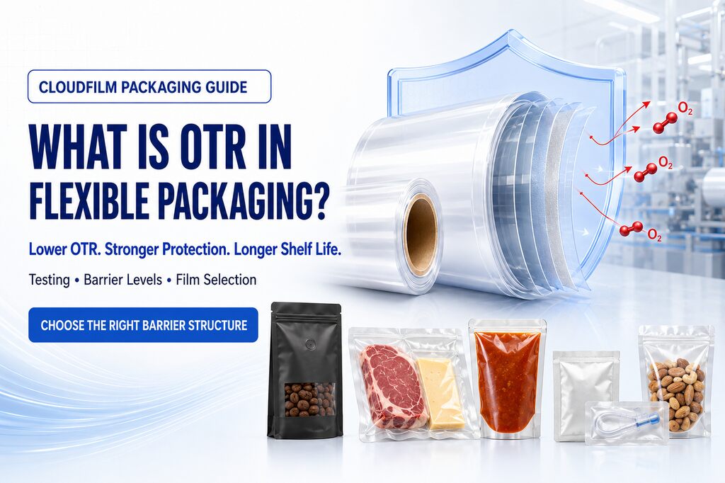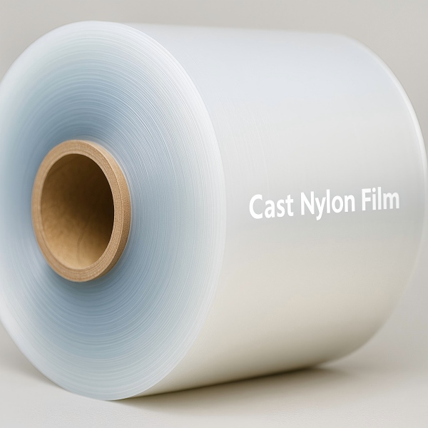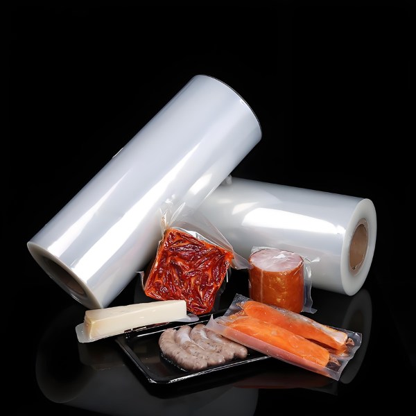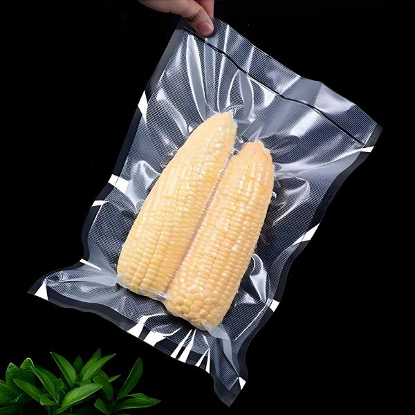
PE/PA/PE thermoforming film is widely evaluated as a flexible bottom web for vacuum and modified-atmosphere packs containing meat, processed food, cheese, seafood and selected industrial products. The bottom web is heated, drawn into cavities, filled and sealed to a compatible top web. Its job is therefore more demanding than simply surviving as a flat sheet: it must unwind evenly, heat uniformly, stretch without weak corners, hold the required cavity, protect the product after thinning and create a dependable seal at production speed.
A useful purchase specification cannot be reduced to “nylon PE forming film, 90 microns.” It must connect the film to the product, cavity geometry, machine recipe, top-web sealant, target shelf life and finished-pack tests. This application guide explains how to prepare that specification. For the broader material background, first review the PE/PA/PE film buyer guide, then compare the project with CloudFilm’s available PE/PA/PE film for thermoforming bottom webs.

What Is a Thermoforming Bottom Web?
On a roll-fed thermoforming form-fill-seal line, the lower film is indexed through a heating and forming station. Vacuum, pressure, plug assistance or a combination of these forces draws the softened web into a mould. The formed cavities move to loading, where product is placed manually or automatically. A top web is then applied, the package is evacuated or gas flushed when required, and heat and pressure create the perimeter seal before cutting separates the packs.
The lower web is called the bottom web, forming web or deep-draw film. These terms describe its process role, not one universal material. Flexible PA/PE film and PE/PA/PE webs, rigid PET- or PVC-based webs, semi-rigid structures and high-barrier EVOH constructions can all be used in thermoforming systems. The correct choice depends on whether the finished pack should be flexible or rigid, vacuum or MAP, peelable or permanently sealed, chilled, frozen or heated, and whether its barrier and puncture risks justify additional functional layers.
Why the bottom web cannot be specified like a flat pouch film
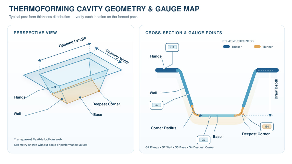
A pouch film usually enters the package near its supplied thickness. A forming web is deliberately stretched, so material moves from the flange and sheet plane into the cavity walls, base and corners. The deepest corner may be much thinner than the incoming roll. That local thinning changes puncture resistance, barrier, appearance and handling strength. The unformed gauge, flat-film OTR and room-temperature puncture result are useful incoming controls, but they do not prove performance in the critical formed areas.
Why PE/PA/PE Is Used for Flexible Thermoforming
PE/PA/PE combines PE-rich surfaces with an internal PA function. The PE portions provide the heat-sealing interface, flexibility and most of the moisture resistance. PA contributes toughness, puncture resistance, gas-barrier support and a useful response to drawing; the nylon film properties guide explains how moisture and conditioning influence those functions. Tie layers are normally required between PE and PA, so the commercial web may contain five, seven or more physical layers even when buyers use the functional name PE/PA/PE.
This structure is attractive when the pack needs a clear, close-fitting flexible cavity rather than a rigid tray. It can support vacuum packaging for meat, poultry, processed products, seafood and cheese, as demonstrated by commercial thermoforming systems that run flexible films for vacuum and MAP formats. It may also be used for industrial parts when compatibility and transport tests are completed. The combination is not automatically suitable for retort, hot-fill or sterilization cycles; those processes require a purpose-designed structure and package-specific validation.
Where PA helps—and where it does not solve everything
The nylon function improves toughness and oxygen barrier compared with a simple PE web, but PA absorbs moisture and its barrier response depends on humidity and conditioning. A highly oxygen-sensitive product or a long ambient shelf-life target may need an EVOH-containing construction, coating, metallization or foil. Use the nylon versus EVOH comparison to define the missing function, and review multilayer EVOH coextruded film when the required OTR cannot be achieved by a PA-only design.
Start With Product and Pack Requirements
The fastest route to a reliable bottom-web recommendation is a clear application brief. Film suppliers cannot infer package risk from the product name alone. A block of boneless cheese, sharp frozen shellfish and a sliced cooked-meat pack may all use a transparent cavity, yet they create different puncture, seal-contamination, barrier and display demands.
| Input | Information to provide | Why it changes the film decision |
| Product | Composition, fill weight, dimensions, fat or oil, moisture, sharp points and particulate contamination | Sets puncture, chemical-compatibility, seal and barrier risks |
| Package atmosphere | Vacuum, MAP gas mix, residual oxygen target or simple air pack | Changes top-web choice, barrier target, headspace and leak sensitivity |
| Distribution | Chilled, frozen or ambient temperature; freeze/thaw; route; secondary pack; handling | Determines low-temperature toughness, abrasion and transport validation |
| Shelf life | Target days, failure mode, temperature and current package result | Converts a vague “high barrier” request into a testable target |
| Consumer opening | Permanent seal, controlled peel, reclose feature or cut-open pack | Defines the top/bottom sealant pairing and failure mode |
For food projects, also define the destination market and required food-contact documentation. For medical or pharmaceutical applications, do not transfer a food-grade specification into a sterile-barrier project. Sterilization method, microbial-barrier system, device geometry, seal design and formal validation belong to a separate qualification programme.
Describe the Cavity, Not Only the Draw Depth
“Draw depth: 60 mm” is not enough to select a forming web. A narrow, steep cavity with sharp bottom corners can impose more local stretch than a wider cavity of the same depth. The supplier and machine technician need the opening length and width, base dimensions, depth, corner and edge radii, wall angle, flange width, cavity pitch and number of cavities per index. A drawing or formed sample is better than a depth number alone.
Use draw ratio as a comparison tool, not a universal guarantee
Converters may estimate an area draw ratio by comparing the approximate formed surface area with the original opening area. This is useful when screening two cavities, but it can hide the local strain at corners and around product features. Different companies and machine suppliers may calculate draw ratio differently. State the method used, then confirm the actual thickness map on the trial line. Do not approve a film merely because a supplier quotes a maximum depth or ratio without the cavity geometry and machine conditions.
| Cavity field | Record on the trial brief | Risk if omitted |
| Opening and base | Length, width and any taper from flange to base | Depth alone understates total stretching |
| Depth and wall angle | Nominal depth, draft angle and vertical wall sections | Spring-back, thin walls or incomplete forming |
| Corner radii | Flange, sidewall and base radii at the tightest point | Severe local thinning, whitening or puncture |
| Flange and seal land | Flat width, texture, contamination path and cutting clearance | Wrinkles, narrow seals or channel leaks |
| Tooling and assistance | Vacuum/pressure arrangement, plug material, plug stroke and mould temperature | Supplier assumes a different material distribution mechanism |
Specify Film Structure and Thickness
CloudFilm currently lists PE/PA/PE film at approximately 50–150 μm total thickness, about 300–2000 mm width and 3-inch or 6-inch cores. The same product page identifies 70–120 μm as a common direction for deep-draw thermoforming and frozen-meat applications. These figures describe a customizable supply range and a screening direction; they are not a promise that every cavity, product or machine can use every gauge within that range.
Total gauge is only the first layer of the specification
Two 100 μm films can form differently because the PA type, PE blends, tie resins, layer ratios and cooling history differ. A higher PA proportion may improve some mechanical and barrier properties but can change stiffness, moisture response, forming window and cost. A thicker PE seal layer may provide a broader seal window or better contamination tolerance, but the complete web still needs sufficient internal adhesion and post-form toughness. The approved specification should therefore identify the supplier grade or agreed functional structure as well as total thickness.
| Screening gauge | Possible trial direction | Reasons to move thicker or tougher | Approval evidence |
| 50–70 μm | Shallow cavities, light products and modest handling risk | Corner thinning, sharp product, frozen handling or seal abuse | Corner gauge, leak rate and distribution result |
| 70–100 μm | Many flexible vacuum and medium-draw development trials | Deeper cavity, tighter radius, heavier fill or rough logistics | Stable forming window and filled-pack testing |
| 100–120 μm | Deep draw, frozen food, cheese blocks or higher puncture risk | Severe local stretch, bone or industrial sharpness | Post-form puncture, barrier and transport tests |
| 120–150 μm | Demanding cavities or heavy-duty protection within supplier capability | Use only when data show the lower gauge lacks margin | Cycle time, heating energy, yield and total pack cost |
The ranges above are intentionally cautious. A smaller number is not automatically economical, and a larger number is not automatically safer. Compare usable packages per kilogram, forming scrap, line speed, leaks, product loss and customer complaints. Down-gauging is successful only when the finished package retains an adequate process and distribution margin.
Match the Bottom Web to the Top Web and Seal System
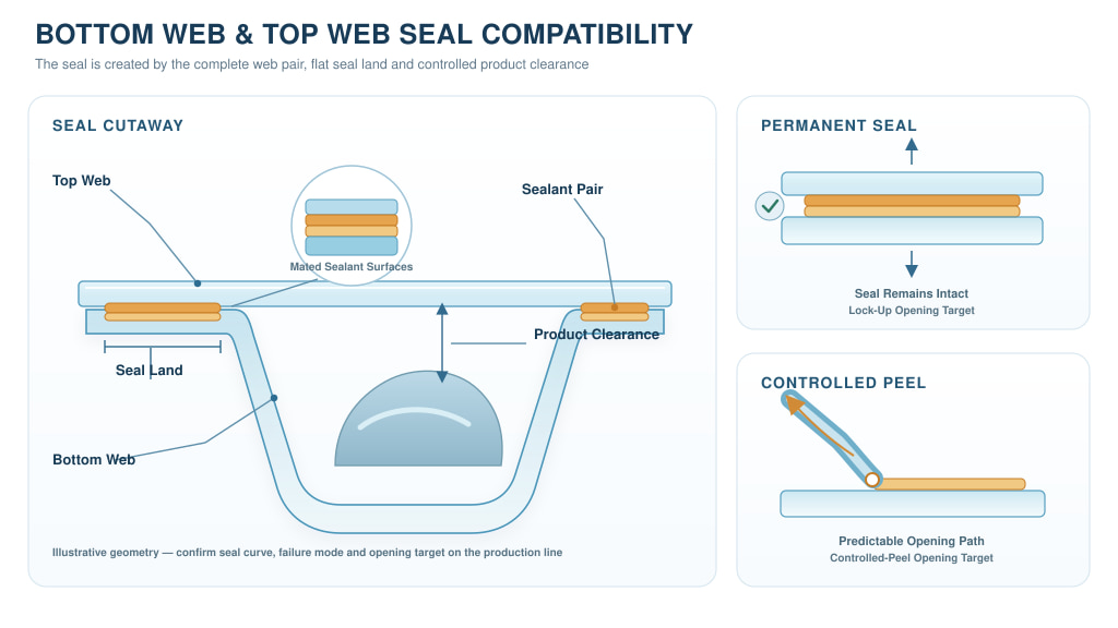
A thermoforming package is a two-web system. The bottom film may form perfectly and still fail if its seal layer is incompatible with the top web. Provide the supplier with the current top-web structure, sealing side, thickness, surface treatment, printing or lamination construction and whether the pack needs a permanent weld or controlled peel. If a replacement bottom web is being evaluated, send both a top-web sample and the existing approved bottom film.
Permanent seal versus peelable opening
Permanent vacuum packs normally prioritize high seal integrity and resistance to channels, product contamination and handling. Easy-open packs require a controlled peel force and a clean, predictable failure path. The peel mechanism may be located in the top-web sealant, bottom-web seal layer or an interfacial pairing; CloudFilm’s easy-peel film range shows one related material direction. Do not request “easy peel” without defining the target force, peel consistency, opening temperature, ageing period and acceptable visual failure mode. A seal that is easy to open but leaks in distribution is not a successful design.
| System item | Specify | Confirm in the trial |
| Top-web sealant | Material family, intended seal side and supplier grade | Seal curve and failure mode across the operating window |
| Opening type | Permanent, peelable, reclosable or cut-open | Peel force after production, ageing and cold storage |
| Barrier balance | OTR/WVTR target for both webs and the finished pack | Headspace oxygen, shelf life and seal leakage |
| Dimensional response | Shrink, curl, thermal stability and web tension | Flat flange, registration and package appearance |
| Seal contamination | Likely juice, oil, powder, crumbs or wrinkles | Deliberate contamination challenge at production speed |
Define the Thermoforming Process Window
A supplier cannot recommend a robust forming grade from machine brand alone. Record the machine model, forming area, indexing length, heating method, upper and lower heater zones, heating time, forming vacuum or pressure, plug-assist details, mould temperature, cooling time, web speed and target cycles per minute. If the current material runs well, record its recipe and use it as a controlled comparison—not as an assumption that the new film must use identical settings.
Map a window instead of chasing one “best” temperature
Heater displays do not necessarily equal the film temperature, and different machines transfer heat differently. Begin within the supplier’s safe recommendation, then vary one factor at a time. At each condition record cavity definition, corner whitening, wall uniformity, spring-back, flange flatness, web release, cycle time and scrap. The approved recipe should sit inside a stable region, not at the edge where a small change in ambient temperature, roll age or line speed creates defects.
Separate material, tooling and machine causes
Insufficient forming can result from inadequate heat, short heating time, blocked vacuum, poor plug timing, excessive web tension or a film that is too stiff for the cavity. Thin corners can result from cavity geometry, heater imbalance, plug design or material distribution—not only low total gauge. When a defect appears, keep the film lot, machine recipe and mould clean state traceable so the team can change one controlled variable rather than raising heat or thickness blindly.
Specify Roll Dimensions and Unwind Details
A technically suitable resin structure can still stop production if the roll does not fit the line. State the finished width and tolerance, core inner diameter and length, maximum roll outside diameter, maximum net weight, film length if controlling, winding direction, seal side, treatment side, splice number and splice marking. Also define roll hardness, edge alignment, telescoping limit, core projection, label information and pallet protection where these affect automatic loading or export transport.
CloudFilm lists approximately 300–2000 mm width and 3-inch or 6-inch cores for the current PE/PA/PE range, but the final roll build must match the customer’s unwind and lifting equipment. Narrow custom widths, very large OD, uncommon core lengths or strict no-splice rules may affect MOQ, production yield and lead time. Include these details in the RFQ rather than asking for them after the price is agreed.
Control side orientation
The two PE-rich faces may not be functionally identical. One surface may be optimized for sealing, while the other carries a different slip package or corona treatment. Use a roll diagram to show which side contacts the mould, product and top web and whether the functional side faces inward or outward on the roll. Printed arrows, colour-coded core labels or an agreed side code reduce installation errors during a trial.
Test Post-Form Thickness, Barrier and Mechanical Integrity
The most important material question is not only “What was the incoming thickness?” but “Where did the material go after forming?” Cut representative cavities and measure the flange, upper wall, mid-wall, lower wall, base centre and each critical corner. Record the minimum, average and location. A simple local retention percentage—measured formed thickness divided by incoming thickness × 100—can help compare trial conditions, but there is no universal acceptable percentage for every product and cavity.
| Location or test | What to record | Decision it supports |
| Incoming web | Cross-web profile, average gauge and edge condition | Separates supplied variation from forming redistribution |
| Flange | Thickness, flatness, wrinkles and seal contamination | Confirms a stable seal land |
| Walls and base | Gauge distribution, haze, whitening and pinholes | Shows heating and material distribution balance |
| Deepest corners | Minimum gauge, puncture, flexing and interlayer integrity | Locates the likely mechanical and barrier weak point |
| Formed barrier | OTR/WVTR or finished-pack oxygen study under stated conditions | Tests the real package rather than extrapolating flat-film data |
PA barrier and mechanical response are sensitive to conditioning and humidity, while stretching changes the amount and distribution of material. Compare barrier data only when test method, temperature, relative humidity, specimen orientation and conditioning are stated. For shelf-life-critical products, use the formed and sealed pack in a product study instead of treating a flat-film TDS value as a shelf-life guarantee.
Validate Seal Integrity and Finished-Pack Performance
Build a seal curve by making packages at several temperatures while holding pressure, dwell time and web combination constant. Measure seal strength and record the failure mode. ASTM F88/F88M is a recognized method for measuring the force required to separate a strip containing a flexible-material seal and for identifying specimen failure mode. The project must still define specimen width, grip configuration, conditioning and acceptance limits so results remain comparable.
Seal-strength testing should be paired with package-integrity methods. Depending on the pack, programme and sensitivity needed, the team may use vacuum decay, pressure decay, gross-leak bubble testing, dye or tracer methods, burst/creep testing, headspace analysis or shelf-life monitoring. ASTM F2096, for example, covers gross-leak detection by internal pressurization and can be used for tray and pouch packages, but it is destructive and is not a universal microleak method. Select the method for the actual failure risk and validate it for the package.
Test deliberate production challenges
Clean, hand-made laboratory seals often overstate line performance. Include the normal range of product temperature, juice or oil, crumbs, wrinkles, fill height, operator loading and cycle speed. After sealing, condition packs at the intended chilled or frozen temperature, then perform handling, drop, vibration, abrasion and compression tests that reflect distribution. Track leakers by location: seal channel, corner puncture, top-web damage, cut edge or material pinhole. The location determines the corrective action.
Typical Starting Directions by Application
The following table is a development screen, not a finished specification. The actual cavity, product hazard, barrier target and line trial control the choice.
| Application | Main film challenge | Starting direction | Must validate |
| Boneless chilled meat | Juice contamination, vacuum retention and handling puncture | Clear forming-grade PE/PA/PE with a robust permanent-seal system | Seal curve, leak rate and shelf life |
| Frozen meat or poultry | Low-temperature impact, abrasion and sharp frozen edges | Tougher gauge or layer balance selected after deep-freeze conditioning | Frozen drop, corner puncture and freeze/thaw |
| Cheese blocks or slices | Aroma, oxygen, clean presentation and opening experience | Clear bottom web matched to permanent or peelable top web | Cheese-specific respiration, peel and shelf life |
| Seafood | Shell or bone puncture, drip and oxidation | PA-toughened web; consider higher barrier when the shelf-life model requires it | Actual-product puncture, headspace and cold-chain test |
| Industrial component | Sharp edges, oil contact and export vibration | Heavy-duty structure after chemical-compatibility screening | Compatibility, abrasion, puncture and transport simulation |
For meat and frozen products, the broader frozen meat packaging guide helps connect film selection to bone protection and cold-chain distribution. For dairy projects, use the cheese packaging guide to avoid applying one barrier and opening strategy to every cheese type.
Common Thermoforming Defects and Corrective Actions
| Observed defect | Possible causes to investigate | Controlled response |
| Incomplete cavity or spring-back | Insufficient or uneven heat, vacuum restriction, short forming/cooling time, high stiffness | Check actual heater output, vacuum path, timing and mould temperature before changing film |
| Thin or whitening corners | Tight radius, heater imbalance, poor plug timing, excessive local stretch or unsuitable layer balance | Map gauge, adjust zoned heat/plug/tooling, then compare a tougher or higher-gauge grade |
| Web breaks or pinholes | Cold spot, edge damage, excessive tension, contamination or severe draw | Inspect roll edges and heater zones; reduce tension; retain defect location and lot |
| Wrinkled or distorted flange | Overheating, unstable tension, poor clamping, web curl or top/bottom shrink mismatch | Check web handling, clamping and thermal balance before raising seal pressure |
| Weak or channelled seals | Wrong seal pair, low dwell/pressure, contamination, flange wrinkles or jaw variation | Build a seal curve, inspect failure mode and run deliberate contamination trials |
| Layer separation or bubbles | Tie-layer weakness, excessive local stress, overheating, moisture or incompatible construction | Confirm location and conditioning; test interlayer integrity; escalate to supplier change control |
A defect table is a starting hypothesis, not proof of root cause. Keep photographs, roll and cavity position, machine settings, time, operator and product lot. If the same defect always appears in one cavity, investigate tooling and heater zones. If it follows the roll across cavities, investigate gauge profile, winding, resin balance or roll damage. The flexible packaging quality control guide provides a broader incoming and finished-pack control framework.
RFQ and Approval Specification Checklist
Use the RFQ to collect facts, and use the approval specification to freeze the result of the successful trial. Avoid turning unverified supplier “typical values” into guaranteed limits without an agreed method and tolerance.
| Specification block | Fields to define | Approval record |
| Application | Product, pack dimensions, atmosphere, storage, shelf life and market | Approved product family and limits |
| Film construction | Supplier grade, functional structure, nominal thickness, tolerance and side functions | TDS, sample and golden roll code |
| Cavity and machine | Drawing, depth, radii, tool, heater zones, plug, pressure/vacuum and speed | Approved recipe window and defect limits |
| Top-web system | Top-web grade, seal pair, permanent/peel target, jaw pressure, dwell and temperature range | Seal curve and failure mode |
| Roll build | Width, core, OD, weight, direction, side, splice, edge and pallet | Approved drawing and roll label |
| Performance | Gauge profile, post-form minimums, seal, leak, puncture, barrier and distribution tests | Method, conditioning, sample size and limits |
| Compliance and control | Food-contact declarations, traceability, COA items and change notification | Signed specification and reapproval rule |
Trial-Roll Validation Plan
- Document the incumbent film, product, cavity drawing, top web, machine, roll build and current recipe before the trial.
- Inspect the trial roll for label identity, width, gauge profile, edge damage, winding, core, side orientation and splice marking.
- Run a short conservative setup, then map a controlled forming window across heater, time, plug and vacuum/pressure settings.
- Measure flange, wall, base and corner thickness from every critical cavity position; photograph whitening, pinholes or separation.
- Pair the bottom web with the production top web and build a seal curve at stated pressure and dwell time.
- Run at target production speed long enough to observe tracking, roll change, blocking, release, scrap and operator interventions.
- Fill the actual product or a justified equivalent and challenge normal contamination, fill position and product temperature.
- Condition finished packs at the real chilled, frozen or ambient conditions; test seal, leak, puncture and distribution performance.
- Complete barrier or shelf-life validation where product quality depends on oxygen or moisture transmission after forming.
- Freeze the successful material grade and process window, retain samples and require notification before material or construction changes.
A4 sheets can help compare clarity, identify layers, run small seal tests or collect limited laboratory data. They cannot prove roll tracking, blocking, heating uniformity, draw balance or sustained cycle speed. A trial roll is normally necessary before commercial approval of a machine-critical bottom web.

How to Evaluate a Thermoforming Film Supplier
Ask for application questions before accepting a recommendation
A capable supplier should request the product, cavity, machine, top web, storage condition and roll details. A rapid promise based only on thickness and width transfers the technical risk to the buyer. The supplier does not need to disclose a proprietary recipe, but it should explain the functional structure, intended side, expected use and variables that still require a line trial.
Review data discipline and change control
Confirm how thickness profile, mechanical properties, COF, treatment, interlayer adhesion, barrier and seal performance are controlled. Ask which items appear on the certificate of analysis and which are periodic qualification tests. Roll labels should link the product to a production lot and quality record. Agree whether resin-family, functional-layer, additive or manufacturing-route changes require prior notification or reapproval.
Evaluate roll and export capability
Thermoforming lines can be sensitive to roll edge, hardness, telescoping, width and side orientation. For international supply, review moisture protection, core strength, pallet design, container loading, labels and complaint-response process. A slightly lower film price can be erased by one line stop, a high leak rate or a damaged export pallet. Compare total acceptable packs, not price per kilogram alone.
Frequently Asked Questions
Is PE/PA/PE the same as PA/PE thermoforming film?
They use the same main polymer families, but the names do not guarantee the same physical construction or side functions. PE/PA/PE usually signals PE-rich surfaces with PA inside; PA/PE may describe an asymmetrical coextrusion or laminate. Approve the supplier grade, functional layers and seal side rather than substituting by name.
What thickness is common for a thermoforming bottom web?
CloudFilm lists 50–150 μm as its current customizable PE/PA/PE range and identifies 70–120 μm as a common direction for deep-draw and frozen-meat applications. Final gauge depends on cavity geometry, product weight and sharpness, temperature, top web, line conditions and post-form tests.
Can a supplier select film from draw depth alone?
No. Provide opening and base dimensions, depth, corner radii, wall angle, flange, tool type, plug assistance and machine recipe. A narrow cavity with tight corners can create more local thinning than a wider cavity of the same depth.
What is draw ratio?
It is a way to compare how much the original web area must expand to create the cavity. Calculation methods vary and an overall ratio can hide severe corner strain. State the method, then verify the post-form thickness map and finished-pack performance on the actual line.
Should I specify a minimum corner thickness?
Yes when corner failure is a critical risk, but derive the value from validated trials rather than copying another project. Define the measurement location, instrument, sample conditioning, number of cavities and acceptance method.
Does flat-film OTR remain the same after forming?
Do not assume it does. Forming redistributes and thins the functional layers, and PA barrier also responds to humidity. Use formed specimens or finished-pack studies under stated conditions when shelf life depends on barrier performance.
How do I know whether the top web will seal to the bottom web?
Identify both sealing surfaces and build a seal curve across production temperature, pressure and dwell. Record failure mode and test aged packs. For easy-open designs, also define target peel force and opening consistency.
Can PE/PA/PE be used for MAP packs?
Yes, a suitable bottom web can be paired with a compatible barrier top web for MAP, but the gas mix, residual oxygen, headspace, seal integrity and shelf-life target must be validated. A leak can dominate the package regardless of flat-film barrier.
Is it suitable for frozen meat?
Suitable grades are commonly evaluated for frozen meat because PA adds toughness and PE provides sealing. Condition filled packs at the actual storage temperature and test corner puncture, seals, drops, abrasion and freeze/thaw. Bone guards or another structure may still be needed for severe hazards.
Can it be used for cheese thermoforming packs?
Yes, but the correct barrier and opening design depend on cheese type, maturation, gas generation, moisture, storage and shelf life. Test the actual cheese and top-web combination rather than using one generic structure for every dairy product.
Is a thicker film always easier to thermoform?
No. Extra gauge can add margin, but it can also require more heating, affect cycle speed and increase material use. Layer balance, heater distribution, plug design, cavity geometry and web tension may be more important than total thickness.
Why does the formed cavity turn white?
Whitening can indicate severe local stretch, an unsuitable forming temperature, poor heater balance, layer stress or moisture-related behaviour. Map the defect by cavity and location, measure thickness and change one controlled process variable at a time before changing the film.
Are A4 samples enough?
No for final machine approval. They can support basic material, optical and sealing checks, but they do not prove roll handling, blocking, heating balance, cavity distribution or sustained production speed. Use a trial roll for a new bottom web.
What details are needed for a quotation?
Provide product and pack format, cavity drawing, machine model, top web, current structure and thickness, storage and shelf life, width, core, OD or roll weight, winding direction, monthly volume, destination and required compliance. A current roll label and formed sample accelerate the recommendation.